ISBM Process Fundamentals and Cycle Decomposition
How Does the Injection Stretch Blow Molding Cycle Work Step by Step?
A definitive chronological walkthrough of every station, every motion, and every thermodynamic event that transforms a PET pellet into a finished, biaxially oriented container within a single integrated manufacturing cell.
Deconstructing the ISBM Cycle: A Chronological Engineering Narrative
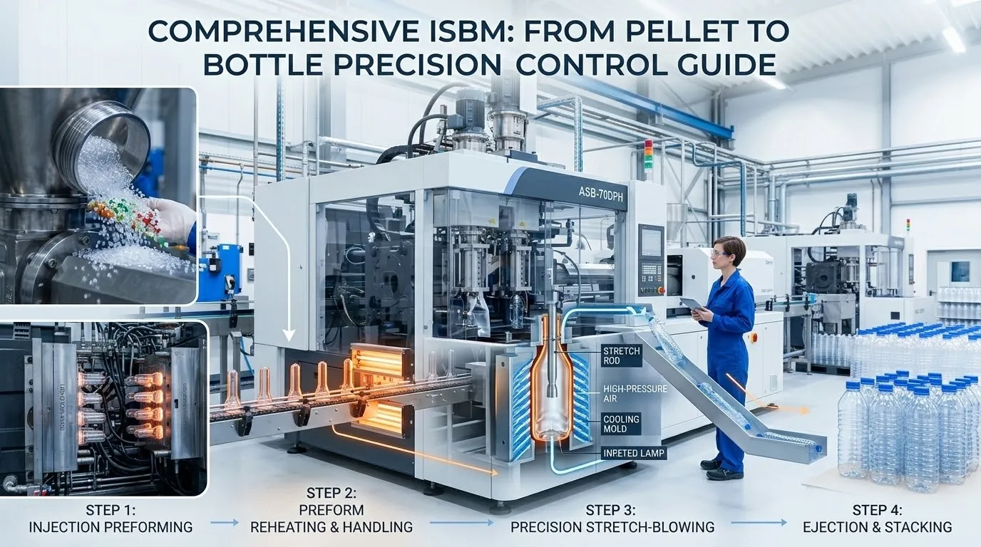
The Injection Stretch Blow Molding cycle is a precisely choreographed sequence of mechanical motions, thermal exchanges, and pneumatic events that unfolds within the compact architecture of a single machine cell. For process engineers, machine operators, and manufacturing managers, a step-by-step understanding of exactly how the ISBM cycle works is not merely academic knowledge. It is the essential mental model upon which effective troubleshooting, cycle time optimization, and quality control are built. Every second of the cycle, every movement of the rotary table, every descent of the stretch rod, and every burst of blow air serves a specific thermodynamic purpose that contributes to the transformation of a simple test-tube-shaped preform into a high-performance, biaxially oriented container. At ہمیشہ کی طاقت, a globally recognized Brazilian ISBM manufacturer, our machine designs are the physical embodiment of this cycle, engineered to execute each step with the precision and repeatability that modern packaging markets demand.
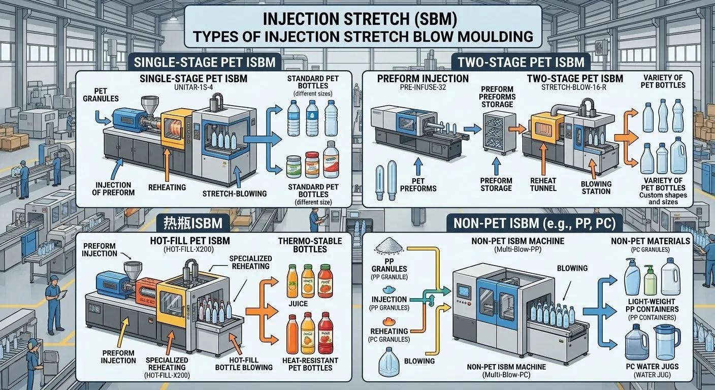
The single-stage ISBM cycle is organized around a rotary indexing table that transports preforms sequentially through four primary stations: the injection station, the conditioning station, the stretch-blow station, and the ejection station. In a four-station machine like the EP-HGY150-V4 4-اسٹیشن مشین, the table rotates 90 degrees between each cycle, and all four stations operate simultaneously. While one set of preforms is being injected, another set is being thermally conditioned, a third set is being stretched and blown into containers, and a fourth set of finished containers is being ejected. This parallel processing architecture is what gives single-stage ISBM its impressive productivity. In a six-station machine like the EP-HGYS280-V6, two additional stations provide extended thermal conditioning for complex container geometries. This comprehensive technical narrative will walk through each step of the ISBM cycle in chronological order, explaining the physics occurring at each stage, the critical machine parameters that govern that step, and the quality implications of deviations from the optimal settings.
By the end of this guide, the reader will possess a complete mental model of the ISBM cycle, enabling them to visualize the process in real-time as they stand before a running machine, and to diagnose and correct production issues with confidence and precision.
پہلا مرحلہ: رال پلاسٹکائزیشن اور پریفارم انجیکشن مولڈنگ
The ISBM cycle begins at the injection station, where solid PET pellets are transformed into a precisely shaped, amorphous preform that encodes the material distribution blueprint for the final container.
Pellet Drying, Melting, and Melt Homogenization
Before the cycle even begins, PET pellets must be rigorously dried in a desiccant dehumidifying dryer to a moisture content below 50 parts per million. Undried PET will undergo hydrolysis in the barrel, permanently degrading the polymer and causing hazy, brittle containers. The dried pellets gravity-feed from the hopper into the throat of the injection barrel. Inside the barrel, a reciprocating screw rotates, driven by either a hydraulic motor or, on advanced machines like the EP-HGY150-V4-EV, a precision servo motor. The screw conveys the pellets forward along the barrel. External heater bands wrapped around the barrel provide conductive heat, while the compression of the pellets by the decreasing channel depth of the screw generates frictional shear heat. The combined thermal energy melts the PET into a homogeneous, viscous fluid. The screw has a non-return valve at its tip that prevents the melt from flowing backward during the injection stroke. As the screw rotates and plasticates the material, it is pushed backward by the accumulating melt pressure, building a precise shot of molten PET in front of the screw tip. Once the shot size is reached, the screw rotation stops, and the injection phase begins.
High-Pressure Injection and Rapid Amorphous Quenching
The screw now acts as a plunger, driven forward by the injection cylinder or servo motor. The molten PET is forced under high pressure, typically 500 to 1500 bar depending on the preform design and material viscosity, through the hot runner manifold. The hot runner is a heated distribution network that splits the single melt stream from the barrel into multiple streams, each feeding an individual injection nozzle that fills a preform cavity. The melt enters the water-cooled steel cavity of the preform mold through a pinpoint gate at the base. The injection mold is clamped shut with sufficient force to resist the injection pressure and prevent flash. The molten PET contacts the cold mold walls, which are chilled by circulating water at 6 to 10 degrees Celsius through conformal cooling channels. The melt is violently quenched, freezing the polymer chains in their tangled, disorganized amorphous state before they have time to crystallize. This rapid quenching is the most critical thermodynamic event in the entire cycle for achieving optical clarity. A hold pressure is applied after the cavity is filled to compensate for the volumetric shrinkage of the cooling plastic, ensuring the preform replicates the cavity dimensions precisely. The preform solidifies, and the injection mold opens. The preform, still containing significant latent core heat, is now ready for transfer to the next station.
Step Two: Rotary Indexing and Preform Thermal Conditioning
Once the injection mold opens, the preform is transferred to the conditioning station by the rotary indexing table, where its temperature is precisely adjusted for optimal stretching behavior.
🤖Robotic Clamp Engagement and Precision Indexing
As the injection mold opens, robotic transfer clamps mounted on the rotary table engage the neck ring of the still-hot preforms. These clamps grip the preforms securely by the neck finish, the only part of the preform that is fully cooled and dimensionally stable. The rotary table then indexes precisely, rotating the preforms to the conditioning station. The indexing motion must be rapid, vibration-free, and repeatable to within microns. Any positioning error will cause the preforms to be misaligned in the conditioning pots, leading to uneven heating and subsequent wall thickness variation. The indexing mechanism on modern ISBM machines is driven by a servo motor or a precision hydraulic rotary actuator, ensuring smooth, accurate motion. The preform, still carrying significant latent heat from the injection process, now enters the conditioning station. The thermal continuity of the single-stage process is exploited here. Because the preform has not cooled to room temperature, the conditioning station only needs to add or subtract relatively small amounts of thermal energy to achieve the target stretching temperature, contributing directly to the energy efficiency of the ISBM cycle.
🌡️Conditioning Pot Engagement and Zonal Thermal Profiling
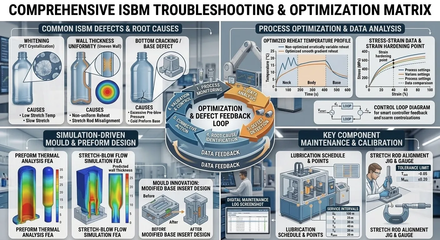
At the conditioning station, the preforms are inserted into steel conditioning pots that are precisely contoured to cradle their exterior. These pots are not simple heaters. They are sophisticated thermal management devices connected to circuits of circulating thermal fluid, typically a specially formulated heat transfer oil. The temperature of each pot is controlled in single-degree increments via dedicated temperature control modules. The conditioning pots heat the preform body to a precise temperature just above the glass transition temperature of PET, typically 95 to 110 degrees Celsius, where the polymer is in a rubbery, pliable state ideal for biaxial stretching. The neck finish is deliberately shielded from the heat and remains cool and rigid. The conditioning pots are divided into independently controllable zones along their length. The shoulder zone, body zone, and base zone can each be set to different temperatures to create a deliberate axial thermal profile. This zonal control is essential for achieving uniform wall thickness in the final container. For complex container shapes, the six-station EP-HGYS280-V6 provides two sequential conditioning stations, allowing an extended, stepped thermal profile. The conditioning time is a critical cycle parameter. It must be sufficient for the temperature to equilibrate through the entire wall thickness of the preform. If the conditioning time is too short, the preform core will be colder than the surface, leading to stress whitening during stretching.
Step Three: The Stretch-Blow Sequence, Axial Elongation and Radial Inflation
The stretch-blow station is the defining phase of the ISBM cycle, where the conditioned preform undergoes biaxial orientation through the coordinated action of the mechanical stretch rod and high-pressure blow air.
⬇️Blow Mold Closure and Stretch Rod Descent
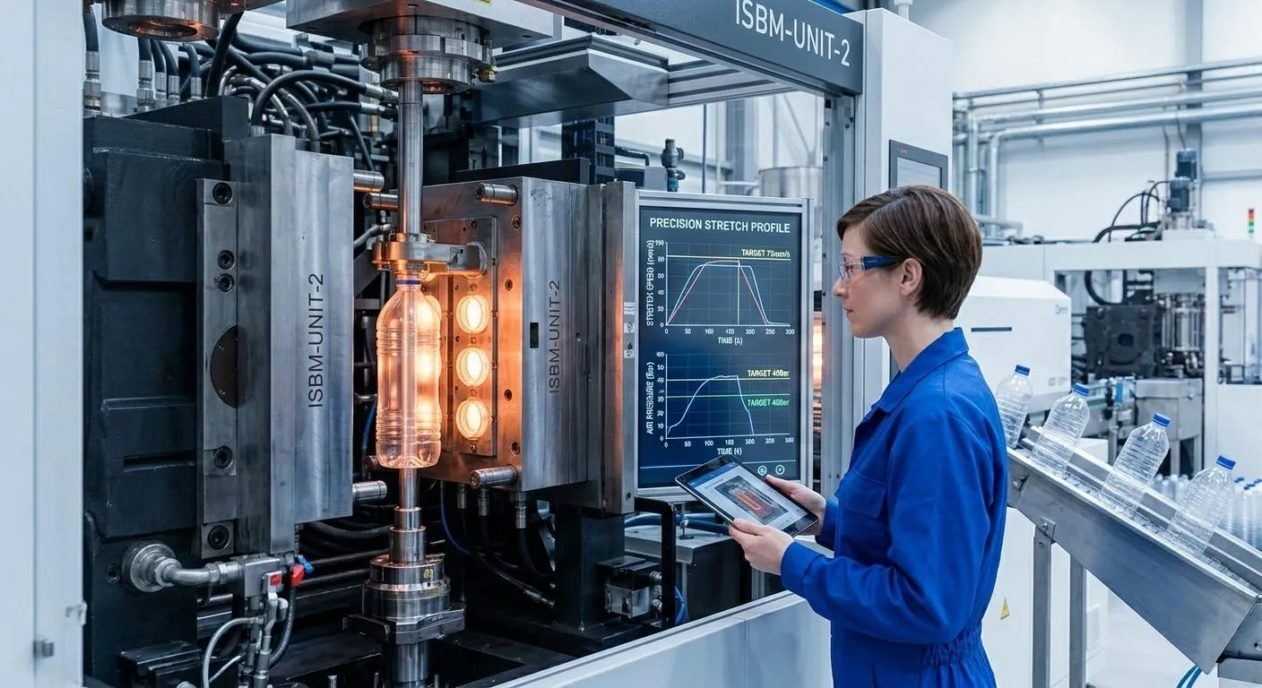
After the rotary table indexes the conditioned preforms into the stretch-blow station, the blow mold closes around them. The blow mold consists of two halves that form the final container shape, plus a base mold that forms the container bottom. The preform is clamped by its neck finish at the top of the mold. With the mold securely closed, the stretch rod descends from above. The stretch rod is a highly polished, precision-ground steel rod, often internally cooled to prevent heat buildup from friction. On hydraulic machines, it is actuated by a pneumatic or hydraulic cylinder. On servo-driven machines like the EP-HGY150-V4-EV, it is driven by a precision ball screw and servo motor, allowing a fully programmable motion profile. The rod enters the preform and contacts the interior of the base. It then pushes downward, forcing the preform to elongate along its vertical axis. The rod velocity, stroke length, and motion profile are critical parameters. A faster descent pushes more material to the base. A slower descent allows more material to remain in the body. The servo-driven rod can execute complex profiles with acceleration, constant velocity, and deceleration segments, gently pinning the material against the mold base without hammering.
💨Pre-Blow Initiation and High-Pressure Final Blow
Simultaneously with the stretch rod descent, a precisely timed sequence of pneumatic events unfolds. The pre-blow is a low-pressure burst of air, typically 2 to 8 bar, that is introduced through the stretch rod or through ports in the mold. The pre-blow timing is adjustable in milliseconds relative to the stretch rod position. Its purpose is to gently begin radial inflation, creating a bubble that the rod can guide downward without the preform touching the cold mold walls prematurely. If the pre-blow is too early or too strong, the shoulder balloons out and thins excessively. If it is too late or too weak, the stretch rod may push the preform into contact with the mold before radial expansion begins, freezing the material in place. Once the stretch rod has fully extended and the pre-blow has initiated the basic shape, the final high-pressure blow air, typically 20 to 40 bar, is injected. This forces the plastic radially outward against the mirror-polished walls of the blow mold cavity, forming every detail of the container. The combined axial and radial stretching induces strain-induced crystallization, creating the biaxially oriented molecular structure that gives the container its strength and barrier properties. The container is held against the chilled mold walls for a brief cooling period to stabilize its dimensions.
Step Four: Container Ejection and the Parallel Processing Architecture
The final step of the ISBM cycle is the ejection of the finished container, but the true genius of the process lies in its parallel architecture where all four stations operate simultaneously.
Blow Mold Opening and Robotic Take-Out
After the container has cooled sufficiently in the blow mold to stabilize its dimensions, the blow air is exhausted, and the mold opens. Robotic take-out arms or mechanical grippers, synchronized with the machine’s indexing cycle, reach into the mold cavity and grasp the finished container by its neck finish. The grippers must be gentle enough to avoid deforming the still-warm container. The container is rapidly transferred out of the mold and placed onto a conveyor or into a collection bin. At this point, the container has completed its transformation from a simple preform to a biaxially oriented, high-clarity, high-strength package. Inline quality inspection systems, including vision cameras and wall thickness sensors, may inspect the container at this point before it enters the downstream handling system. Any rejected containers are automatically diverted to a scrap bin for regrinding and recycling back into the process. The blow mold cavity surfaces are often treated with a non-stick coating or are periodically sprayed with a release agent to ensure the container releases cleanly without sticking. The ejection must be swift and reliable. Any hesitation in the ejection sequence will increase the cycle time and reduce the overall throughput of the machine.
Simultaneous Operation Across All Four Stations
The defining productivity feature of the ISBM cycle is that all four stations operate in parallel. While the injection station is injecting and cooling a new set of preforms, the conditioning station is thermally profiling the previous set, the stretch-blow station is forming containers from the set before that, and the ejection station is removing finished containers from the set before that. The cycle time of the machine is determined by the longest individual station operation, typically the injection cooling time or the conditioning soak time. Optimizing the ISBM cycle involves balancing these station times so that no single station becomes the bottleneck. The parallel processing architecture enables a four-station machine like the EP-HGY250-V4 to achieve cycle times as low as 8 to 12 seconds, depending on the container size and wall thickness. This translates into throughputs of thousands of bottles per hour from a single compact cell. For even higher output, double-row architectures like the EP-HGY250-V4-B multiply the number of cavities per station, producing multiple containers per cycle and achieving throughputs exceeding 80 million bottles per year.
EP-HGY650-V4 extends this parallel processing to the largest preform payloads, handling massive shot weights and high cavitation counts while maintaining the rhythmic precision of the ISBM cycle. Every rotation of the table produces finished containers from the ejection station, and every rotation is a testament to the elegant integration of thermodynamics, kinematics, and pneumatics that defines the injection stretch blow molding process.
Master the ISBM Cycle to Unlock Manufacturing Excellence
The injection stretch blow molding cycle is a masterpiece of process integration, where injection, conditioning, stretching, blowing, and ejection unfold in a synchronized, parallel sequence that transforms a simple polymer pellet into a high-performance container in seconds. Understanding each step of this cycle, the resin plasticization, the amorphous quenching, the precision indexing, the zonal thermal conditioning, the stretch rod descent, the pre-blow and final blow sequence, and the robotic ejection, is the essential knowledge that empowers process engineers and operators to achieve zero-defect production at maximum throughput. At ہمیشہ کی طاقت, our machine platforms, from the versatile EP-HGY150-V4 اعلی پیداوار کے لئے EP-HGY250-V4-B and the precision-engineered اپنی مرضی کے مطابق ون سٹیپ انجکشن اسٹریچ بلو مولڈز, are designed to execute every step of this cycle with the micron-level precision and repeatability that define world-class packaging manufacturing.


