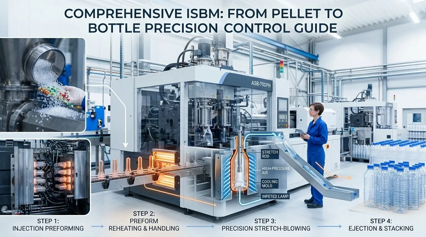
In one-step injection stretch blow moulding, the machine and the mould are not independent variables. They are a matched system — and every significant container quality problem, every production rejection rate, and every cycle time limitation ultimately traces back either to a process parameter error or a tooling design decision. Understanding how ISBM moulds work, what the critical design parameters are, and how mould specification interacts with machine capability is the foundation of producing ISBM containers consistently and at target cost.
This guide covers the complete ISBM tooling picture — the two-element mould set, preform geometry, blow mould cavity design, steel selection by application, cooling circuit engineering, surface finish and its effect on container aesthetics, compatibility with different machine platforms, and the mould development process from container drawing to qualified production tooling.
Whether you are specifying tooling for a new container, replacing an aging mould set, or evaluating whether your existing tooling can transfer to a new machine, this guide provides the technical grounding to make those decisions with confidence.
The Two-Element ISBM Mould Set
Every ISBM production run requires two distinct tooling elements operating in precise dimensional sequence
Preform Geometry: The Most Critical Design Decision
The preform design determines wall thickness distribution, biaxial orientation quality, and container mechanical performance more directly than any other tooling parameter
Preform Weight and Resin Distribution
The total preform weight determines the finished container’s average wall thickness at a given stretch ratio. The distribution of that weight along the preform body — controlled by the core pin profile — determines where material will be available in the blow phase. A well-designed preform concentrates more material in the zones that must stretch the most: the base push-up area and any sharp shoulder or corner features. Inadequate material mass in these zones produces thin spots that fail drop impact testing or create visible sink marks in heavy-wall containers.
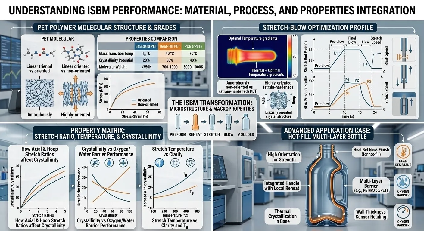
Axial and Hoop Stretch Ratios
The stretch ratio — the ratio of the finished container dimension to the corresponding preform dimension — governs the degree of biaxial orientation achieved in the container wall. For PET, an axial stretch ratio (ASR) of 2.0 to 2.5 combined with a hoop stretch ratio (HSR) of 3.5 to 4.5 produces optimal biaxial orientation, maximising tensile strength, gas barrier, and optical clarity. Ratios below this range result in under-oriented, lower-performance walls. Ratios above it risk stress whitening or material thinning to below the minimum structural thickness.
PETG tolerates a wider stretch ratio range than PET and can be blown at lower temperatures, giving more flexibility in preform design for complex cosmetic shapes. The preform design process begins with the target container dimensions and works backward through the stretch ratio targets to arrive at the required preform body length and diameter.
Gate Design and Gate Vestige
The injection gate is located at the base of the preform and forms the gate vestige visible on the finished container base. In cosmetic containers, the gate vestige is a visible design element — its size, shape, and surface quality affect the premium perception of the container. Ever-Power uses hot tip gate designs that minimise gate vestige size and produce a clean, small injection mark on the container base — consistent with prestige glass-equivalent aesthetics. Cold runner and cold gate systems are not used in ISBM tooling due to the waste material and cycle time implications.
Mould Steel Selection by Application
Steel grade determines mould lifespan, achievable surface finish, corrosion resistance, and polishing behaviour — each critical for specific ISBM applications
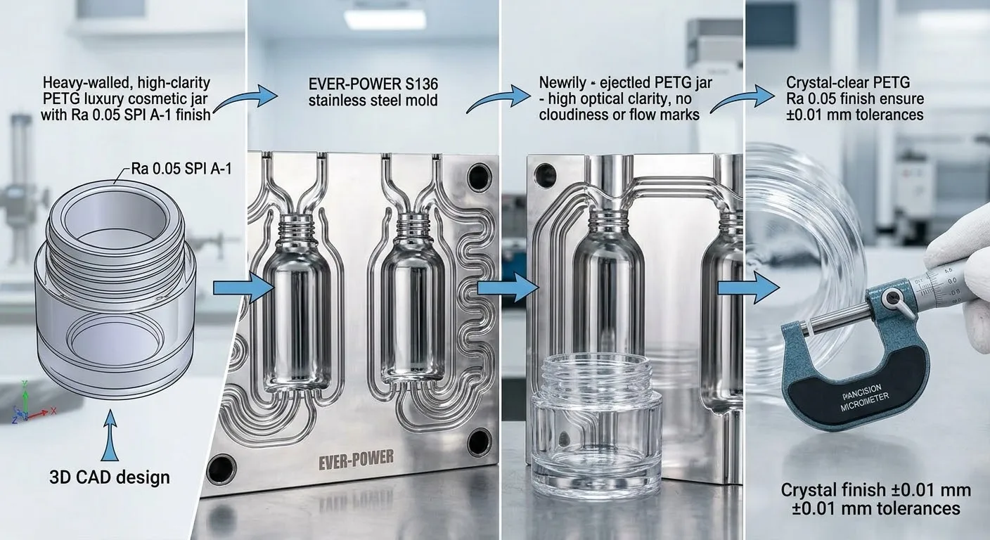
The premier mould steel for luxury cosmetic ISBM applications. S136’s high chromium content provides excellent corrosion resistance against acidic or humid environments, and it polishes to Ra 0.02 — below the SPI A-1 standard, producing a mirror surface quality that competes directly with the finest glass moulds.
H13 is a hot-work tool steel with excellent toughness and resistance to thermal fatigue — critical for high-cavitation injection moulds running PET at high injection pressures and temperatures. H13 moulds can be nitrided to achieve surface hardness of 900 to 1100 HV, extending cavity life in high-volume pharmaceutical production to several million cycles.
P20 is the standard mould steel for general ISBM applications where surface finish requirements are good rather than premium and production volumes are moderate. Its pre-hardened state eliminates the heat treatment step after machining, reducing tooling lead time. P20 is the most economical choice for personal care and food containers where the clarity requirement is high but glass-equivalent mirror finish is not specified.
Beryllium copper (BeCu) alloy is used selectively in blow mould base inserts and corner sections where thermal conductivity is critical. BeCu conducts heat 3 to 4 times faster than tool steel, enabling faster cooling in geometrically complex zones — thick bases, tight radii, and heavy shoulder sections — without increasing cycle time. BeCu inserts are combined with standard steel mould bodies to balance cost and thermal performance.
Cavity Surface Finish: From Mirror to Matte
Surface finish specification is the most consequential aesthetic decision in cosmetic ISBM mould design
The cavity surface finish transfers directly to the container surface. Every mark, scratch, tool path, and texture present on the blow mould cavity will appear on every container produced from that cavity, magnified by the reflective properties of clear PETG or PET. This is why ISBM mould finishing is a specialised craft process requiring skilled polishing technicians working progressively through grit sequences from 400 through 800, 1200, 2000, and finally diamond paste polishing to achieve the finest cosmetic standards.
The choice of finish level is a design decision made early in the tooling specification process. Mirror-finish moulds require more machining time, more polishing time, and more careful handling to avoid surface damage — but they produce a premium container that commands a significantly higher retail price than a comparable satin-finish alternative. The economic case for mirror-finish tooling is well established in prestige skincare and fragrance packaging.
Cooling Circuit Design and Cycle Time
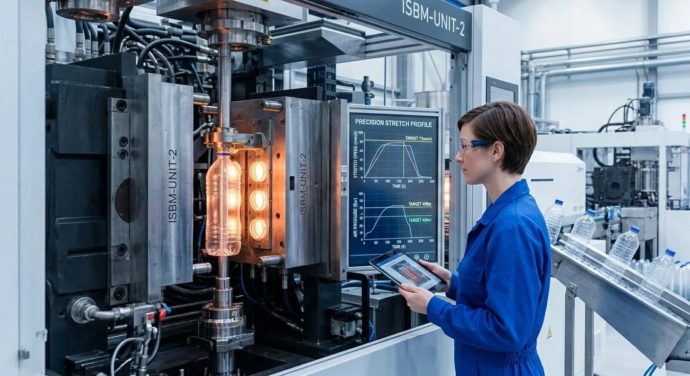
Cooling circuit engineering is the primary determinant of achievable cycle time — and therefore cost-per-container in ISBM production
The blow mould must extract enough heat from the container during the blow phase to solidify the polymer sufficiently that the container retains its shape upon ejection. Insufficient cooling produces thermally deformed containers — ovality variation, base distortion, or shoulder collapse — that fail dimensional inspection. Excessive cooling time increases cycle time and reduces output per shift without improving container quality beyond the minimum acceptable threshold.
Cooling circuit design positions chilled water channels as close to the cavity surface as machining tolerances allow — typically 6 to 10 mm from the cavity surface — and arranges them in a pattern that provides uniform heat extraction across the entire cavity surface. Non-uniform cooling produces differential shrinkage that manifests as container geometry variation, most visibly as ovality in nominally round containers and as wall thickness variation in oval or complex-shaped containers.
For heavy-wall PETG cosmetic jars, the cooling circuit must handle substantially more heat removal per cycle than a standard thin-wall PET container — because the thick preform carries more enthalpy into the blow phase. This is why heavy-wall cosmetic jar production on under-specified moulds consistently produces longer cycle times and higher scrap rates than the machine’s rated cycle time would suggest: the limiting factor is thermal, not mechanical.
Chilled water at this temperature provides the thermal gradient needed for efficient heat extraction from the container wall without producing condensation on the mould exterior in most production environments
The distance from the cooling channel centreline to the cavity surface determines thermal resistance between the water and the container. Closer channels cool faster but reduce the mould wall section available to resist blowing pressure
Cooling time represents 30 to 45 percent of the total ISBM cycle for standard containers. Well-designed cooling circuits reduce this percentage, directly improving output rate without any mechanical machine modification
The Ever-Power Mould Development Process
From container drawing to qualified production tooling — a structured process that eliminates surprises at commissioning
Container Drawing Review
Ever-Power engineers review the customer’s container 3D model or 2D drawing for ISBM feasibility — checking stretch ratios, wall thickness targets, neck thread specification, draft angles, and undercut features. Any design elements that would create production risk are flagged and alternative solutions proposed before tooling design begins.
Preform Design and Simulation
The preform geometry is designed in CAD with wall thickness profiles calculated to achieve the target stretch ratios for the specified resin. For complex shapes or first-of-type containers, material flow simulation is used to predict wall thickness distribution in the blown container before any steel is cut, identifying and correcting distribution issues at minimum cost.
Tooling Design Approval
Complete 2D tooling drawings — injection mould assembly, blow mould assembly, preform drawing, core pin drawing, and cooling circuit schematic — are submitted to the customer for approval before machining begins. This stage ensures dimensional compatibility with the target machine and alignment with the customer’s container specification.
CNC Machining and Finishing
Cavity and core machining on 5-axis CNC machining centres to ±0.01 mm dimensional tolerance. Progressive hand polishing for cosmetic finish moulds through 400, 800, 1200, 2000 grit and diamond paste. Each cavity is dimensionally verified by CMM before assembly. Hot runner system assembled and leak-tested before mould completion.
First Article Trial and Dimensional Report
The completed mould set is trialled on the target machine at Ever-Power’s factory. First article containers are measured dimensionally — external dimensions, neck thread, wall thickness at specified points, weight, and visual inspection for surface defects. A formal first article dimensional report is issued to the customer. Any required adjustments are completed before mould shipment.
Shipment and On-Site Commissioning
Mould set is shipped with a comprehensive documentation package: CAD files, dimensional drawings, first article report, process parameters from factory trial, and maintenance manual. For customers purchasing a machine and tooling together, an Ever-Power commissioning engineer installs and validates the mould on the new machine at the customer’s facility as part of the machine commissioning programme.
Ever-Power Moulds Are Compatible Across All EP Machine Platforms
Every Ever-Power custom mould is designed and validated for a specific target machine — ensuring dimensional compatibility and production performance from day one
Start Your Custom ISBM Mould Project
Send us your container drawing, target machine, resin specification, and annual production volume. Our tooling engineers will assess feasibility, design the preform geometry, and provide a complete tooling proposal including steel grade recommendation, surface finish specification, lead time, and pricing — within 48 hours.
Frequently Asked Questions
Technical specifications and process parameters in this article are based on Ever-Power engineering experience and standard industry tooling practice. Specific mould performance — surface finish achievability, cycle time, and mould life — varies with production conditions and must be confirmed through application assessment. Contact [email protected] or view our custom mould product page to discuss your tooling project.