
Precision Process Control and Diagnostics
How Can You Control Wall Thickness and Uniformity in ISBM?
A comprehensive engineering guide to mastering preform design, thermal conditioning, stretch rod kinematics, and pneumatic timing to achieve micron-level wall thickness consistency in every container.
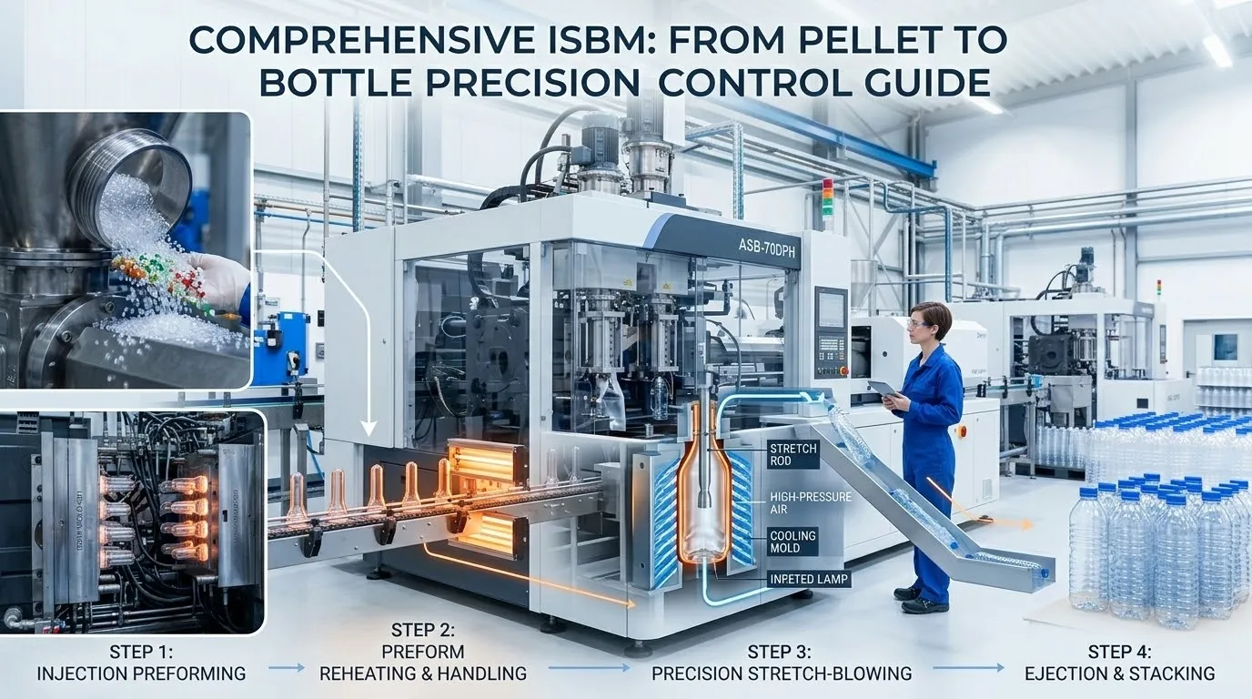
The Imperative of Wall Thickness Uniformity in ISBM Containers
Controlling wall thickness and achieving uniformity across the entire surface of an Injection Stretch Blow Molded container is not merely a quality objective. It is a fundamental manufacturing necessity that directly dictates the structural integrity, barrier performance, material cost, and visual quality of the finished product. A container with a perfectly uniform wall thickness will exhibit optimal top load strength, consistent drop impact resistance, and a flawless glass-like appearance. Conversely, wall thickness variation leads to thin spots that compromise structural integrity under internal pressure or vacuum, thick spots that waste material and increase unit cost, and uneven optical properties that betray a lack of manufacturing precision. At Ever-Power, a premier Brazilian ISBM manufacturer, controlling material distribution is the central challenge around which our entire machine architecture and process engineering philosophy is built.
Wall thickness control in ISBM is a multi-variable problem that spans the entire manufacturing sequence. It begins with the geometric design of the preform, which encodes the intended material distribution. It continues through the thermal conditioning step, where the precise temperature profile of the preform body determines how the material will flow during stretching. It reaches its culmination in the stretch-blow station, where the interplay between the mechanical stretch rod’s axial motion and the pneumatic pre-blow and final blow air pressures and timings shapes the container against the mold walls. Each of these levers interacts with the others in a nonlinear fashion, meaning that wall thickness control is not achieved by adjusting any single parameter in isolation. It requires a systems-level understanding of how preform design, thermal conditioning, and stretch-blow dynamics combine to deliver uniform material distribution. This comprehensive technical analysis will dissect each of these control dimensions, providing process engineers and production managers with the knowledge to diagnose wall thickness problems and implement corrective actions on machines like the EP-HGY150-V4 4-Station Machine.
Mastering wall thickness control is the hallmark of a world-class ISBM operation. It is the difference between producing containers that meet the minimum specification and containers that consistently exceed the expectations of the most demanding brand owners. This guide provides the engineering framework to achieve that mastery.
The Foundation: Preform Design Encodes the Material Distribution
Wall thickness control begins long before the machine is powered on. It starts with the engineering of the preform itself, whose geometry is the blueprint for the final container.
The Axial Thickness Profile as a Predictive Tool
The preform is not a uniform tube. It has a deliberately engineered axial thickness profile where the wall thickness varies along its length. This profile is the primary design tool for controlling the final wall thickness distribution of the container. During stretching, different regions of the preform experience different degrees of axial elongation and radial expansion. The shoulder of the container, which undergoes the most dramatic deformation, will thin out more than the body. To compensate, the preform is designed with a thicker wall in the region that will become the shoulder. The mid-body, if it experiences a more uniform stretch, may be designed with a slightly thinner wall. The base region, where the stretch rod pins the material, may be thickened to provide sufficient material for complex base geometries like petaloid feet. This thickness profile is calculated using finite element simulation software that models the entire stretch blow process, predicting the final wall thickness at every point on the container. The simulation is iterated until the predicted wall thickness meets the specification everywhere. This design process, executed by the mold engineering team for machines like the EP-BPET-125V4, is the single most powerful lever for controlling wall thickness uniformity. A well-designed preform makes achieving uniformity straightforward. A poorly designed preform makes it virtually impossible.
Stretch Ratio Consistency Across the Container Surface
Uniform wall thickness is achieved when the biaxial stretch ratio is consistent across the entire container surface. If one region of the preform stretches by a ratio of 10 while another region of the same initial thickness stretches by a ratio of 6, the resulting wall thickness will be non-uniform. The preform designer aims to design a geometry where, when inflated into the intended blow mold cavity, every region of the preform experiences a similar degree of biaxial orientation. This requires careful coordination between the preform body diameter, the preform length, and the blow mold cavity dimensions. The preform diameter must be chosen such that the radial stretch ratio is within the target range for the material. The preform length must be chosen such that the axial stretch ratio is similarly appropriate. The two ratios should be balanced to avoid extreme anisotropy in the final container properties. For containers with a high degree of asymmetry, such as flat-oval shapes, achieving uniform stretch and therefore uniform wall thickness is particularly challenging and demands the advanced dual-conditioning capability of machines like the EP-HGYS280-V6 to selectively prepare different regions of the preform for differential stretching.
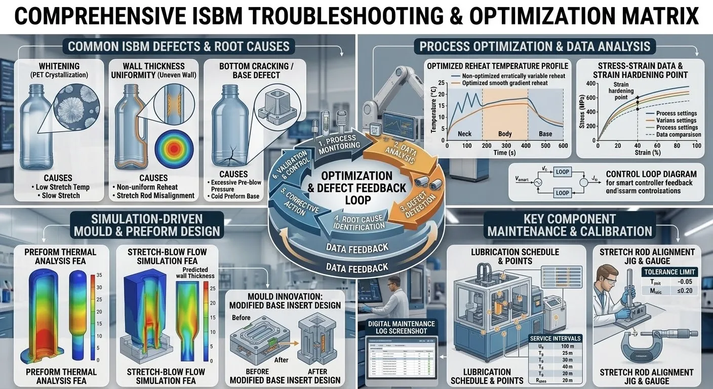
Thermal Conditioning: The Primary Real-Time Control Lever
Once the preform design is fixed, the most powerful real-time lever for controlling wall thickness distribution on the production floor is the thermal conditioning profile of the preform.
🌡️The Physics of Temperature-Dependent Material Flow
The temperature of the preform at the moment of stretching is the dominant factor governing where material flows. A warmer region of the preform is softer and flows more readily under the applied stretch forces. It will stretch more and thin out more. A cooler region is stiffer and resists stretching. It will stretch less and retain more of its original thickness. This simple physical principle is the basis for wall thickness control via thermal conditioning. If a container is emerging with the shoulder too thin and the base too thick, the thermal conditioning of the preform must be adjusted. The conditioning pot temperature in the zone corresponding to the shoulder region is reduced slightly, making that area of the preform slightly cooler and stiffer, so it resists stretching and retains more thickness. Conversely, the zone corresponding to the base is heated slightly more, making it softer and encouraging it to stretch and thin out, providing more material to the shoulder. This zonal temperature control is executed through the conditioning pots, which are divided into independently controllable heating zones along their length. The temperature setpoints for each zone are adjusted in single-degree increments on the machine HMI of platforms like the EP-HGY200-V4, and the effect on wall thickness is observed after the thermal mass of the tooling has stabilized.
🎯Zonal Profiling for Asymmetric and Complex Shapes
For containers that are not simple cylinders, such as flat-oval or highly contoured bottles, the thermal conditioning must often be asymmetric. Different circumferential regions of the preform must be at different temperatures to encourage material to flow preferentially into the more distant regions of the mold cavity. On simpler machines, this is achieved by physically rotating the preform within the conditioning pot to average out any circumferential temperature variations. On more advanced platforms, the conditioning pots can be engineered to deliver a deliberate circumferential temperature profile, selectively heating or cooling specific angular sectors of the preform. This capability is essential for achieving uniform wall thickness in asymmetric containers. The dual conditioning stations of the EP-HGYS280-V6 provide an extended thermal preparation sequence that can be programmed to deliver these complex temperature profiles with high precision, significantly improving wall thickness uniformity in challenging container geometries.
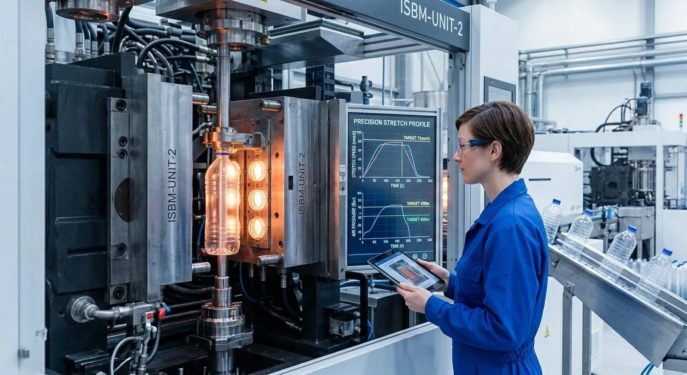
Controlling Material Distribution Through Stretch Rod Kinematics and Pneumatic Timing
The stretch-blow station provides two additional, highly dynamic control levers for wall thickness uniformity: the motion of the stretch rod and the timing and pressure of the blow air.
⬇️Stretch Rod Velocity, Stroke, and Timing
The stretch rod is the primary driver of axial material distribution. When the rod descends, it pushes material from the body of the preform toward the base. The speed at which the rod descends, the distance it travels, and the precise moment it begins its motion relative to the pre-blow air all influence where material ends up. A faster rod descent pushes material more aggressively to the base, potentially leaving the shoulder region thinner. A slower descent allows the material to stretch more evenly. The rod stroke length determines how far the preform base is pushed into the mold base. If the rod extends too far, it can trap excessive material in the base, creating a thick, heavy bottom and a thin body. If it does not extend far enough, the base may not form completely, leaving an unoriented, weak center. On servo-driven machines like the EP-HGY150-V4-EV Full Servo Machine, the stretch rod motion is fully programmable with acceleration, constant velocity, and deceleration segments. This allows the engineer to program a complex motion profile where the rod decelerates as it reaches the end of its stroke, gently pinning the material without hammering it and creating a localized thin spot. Adjusting the stretch rod velocity profile is one of the most effective methods for fine-tuning the axial wall thickness distribution.
💨Pre-Blow Delay, Pressure, and Final Blow Timing
The pneumatic sequence is the second dynamic control lever in the stretch-blow station. The pre-blow is a low-pressure burst of air introduced during the stretch rod’s descent. Its timing and pressure have a profound effect on wall thickness distribution. If the pre-blow is introduced too early, the preform inflates radially before the stretch rod has guided material to the base, causing the shoulder to balloon prematurely and thin out excessively while the base remains thick. If the pre-blow is delayed too long, the stretch rod may force the preform walls into contact with the cold mold, freezing them in place and preventing uniform radial expansion. The pre-blow delay timer, adjustable in milliseconds on the machine HMI, is a critical parameter for achieving uniform material distribution. The pre-blow pressure also matters. A higher pre-blow pressure accelerates radial expansion. The final high-pressure blow must be timed to occur once the preform has been fully elongated by the rod and the pre-blow has initiated the basic shape. The final blow pressure and its ramp rate control how the material is forced into the intricate details of the mold cavity. Machines like the EP-BPET-70V4 provide precise proportional control over these pneumatic parameters, enabling operators to dial in the exact wall thickness distribution required.

Measurement, Inspection, and Closed-Loop Wall Thickness Control
Achieving and maintaining wall thickness uniformity requires precise measurement capability and, increasingly, closed-loop feedback systems that adjust process parameters in real-time.
Manual Sectioning and Thickness Gauging
The traditional method for measuring wall thickness distribution is to physically section a sample container, cutting it into horizontal bands at defined heights, and then using a precision magnetic or Hall-effect thickness gauge to measure the wall thickness at multiple points around each band. This destructive test provides a complete map of the container’s material distribution. The data is plotted against the specified minimum, maximum, and target thicknesses for each region. While accurate, this method is time-consuming and provides only intermittent quality data. It is a critical tool for process setup and for periodic quality audits, but it cannot provide the real-time feedback necessary for continuous optimization. For high-value applications, the data from these measurements informs adjustments to the conditioning temperature profile and stretch rod parameters on machines like the EP-HGY250-V4.
Infrared and Vision-Based Inline Measurement
Modern high-speed ISBM lines increasingly incorporate non-contact inline measurement systems. Infrared absorption sensors can measure the wall thickness of a container as it passes on a conveyor, providing a continuous stream of thickness data without destroying the container. Multi-camera vision systems can also detect geometric deviations that indicate wall thickness problems. These inline systems provide the data density necessary for true statistical process control. The data is plotted on control charts with upper and lower control limits, and alarms are triggered if the process drifts beyond acceptable bounds. On advanced production systems, this inline measurement data can be fed back to the machine controller in a closed loop. The controller can automatically adjust conditioning pot temperatures or pre-blow timing to maintain wall thickness within the specification window. This level of automation transforms wall thickness control from a reactive, operator-dependent activity into a proactive, automated function of the machine.
EP-HGY250-V4-B, must maintain that uniformity across every single cavity. Wall thickness variation between cavities is a sign of imbalance in the hot runner system or variation in the cooling or conditioning of individual cavities. Diagnosing and eliminating cavity-to-cavity variation is a critical aspect of high-volume wall thickness control. This involves checking the melt temperature at each hot runner nozzle, verifying the water flow and temperature in each mold cooling circuit, and ensuring that each conditioning pot is delivering the identical thermal profile. Even a single blocked cooling channel in one cavity will produce a preform with a different thermal history, leading to a container with a different wall thickness distribution. The use of high-quality, precision-manufactured molds like the Custom One-Step Injection Stretch Blow Moulds from Ever-Power minimizes these sources of variation at the design stage.
Achieve Perfect Wall Thickness Uniformity with Integrated ISBM Engineering
Controlling wall thickness and uniformity in ISBM is a multi-faceted engineering discipline that integrates preform design, thermal conditioning, stretch rod kinematics, pneumatic timing, and precision measurement into a coherent process control strategy. Each of these levers must be understood and applied in concert to achieve the micron-level consistency that defines world-class container production. At Ever-Power, our integrated approach to machine design, Custom One-Step Injection Stretch Blow Moulds, and process engineering provides our customers with the tools and the knowledge to master wall thickness control across every container they produce.